The diagram below shows the production of steam using a gas-cooled nuclear reactor. Summarise the information by selecting and reporting the main features, and make comparisons where relevant.
The picture diagram illustrates the making of steam using a gas-cooled nuclear reactor.
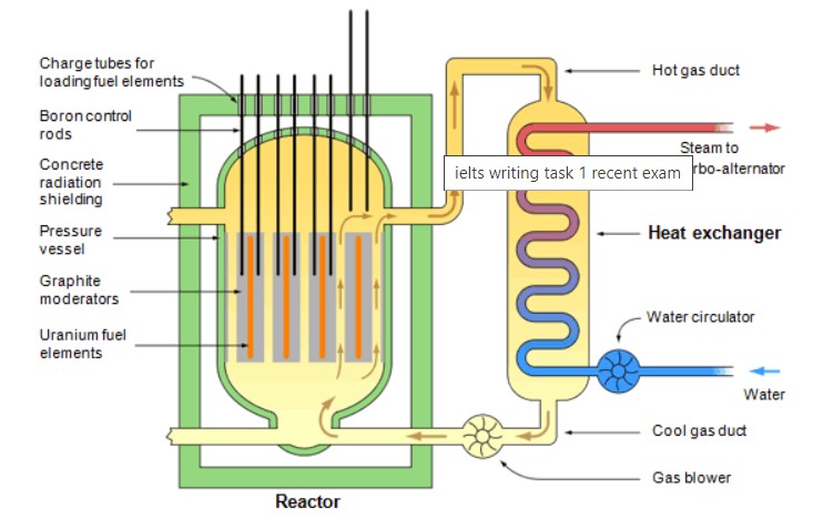
In an overview, there are two main components which are reactor and heat exchanger. A pipeline is connected from heat exchanger to reactor, one is the downside for cool gas duct (passing to the reactor), and another is up to part for hot gas duct (receiving from the reactor). A gas blower is fitted for sending cool gas to the reactor.
The reactor is placed in the concrete radiation shielding. The heart parts of the reactor are uranium fuel elements and graphite moderators. Boron control roads are connected from graphite moderators to concrete radiation shields, which are fixed with charge tubes for loading fuel elements. There is a small space given inside for gas passing from down to up. The whole part is covered by a pressure vessel.
The heat exchanger produces steam from water. The external water pipe is connected to the bottom side of the heat exchanger and fixed a water circulator too. The pipeline passes inside the heat exchanger and exits on the top side, so the steam out through the turbo alternator.
Also Read In Some Countries 18 Is The Legal Age to Vote, to Drive and to Marry
Follow Us on IELTSDATA Twitter